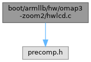
#include "precomp.h"
Include dependency graph for hwlcd.c:

Go to the source code of this file.
Functions | |
| VOID NTAPI | LlbHwOmap3LcdInitialize (VOID) |
| ULONG NTAPI | LlbHwGetScreenWidth (VOID) |
| ULONG NTAPI | LlbHwGetScreenHeight (VOID) |
| PVOID NTAPI | LlbHwGetFrameBuffer (VOID) |
| ULONG NTAPI | LlbHwVideoCreateColor (IN ULONG Red, IN ULONG Green, IN ULONG Blue) |
Variables | |
| PUSHORT | LlbHwVideoBuffer |
Function Documentation
◆ LlbHwGetFrameBuffer()
◆ LlbHwGetScreenHeight()
◆ LlbHwGetScreenWidth()
◆ LlbHwOmap3LcdInitialize()
Definition at line 15 of file hwlcd.c.
16{
17 /*
18 * N.B. The following initialization sequence took about 12 months to figure
19 * out.
20 * This means if you are glancing at it and have no idea what on Earth
21 * could possibly be going on, this is *normal*.
22 * Just trust that this turns on the LCD.
23 * And be thankful all you ever have to worry about is Java and HTML.
24 */
25
26 /* Turn on the functional and interface clocks in the entire PER domain */
29
30 /* Now that GPIO Module 3 is on, send a reset to the LCD panel on GPIO 96 */
33
34 /* Now turn on the functional and interface clocks in the CORE domain */
37
38 /* The HS I2C interface is now on, configure it */
47
48 /*
49 * Set the VPLL2 to cover all device groups instead of just P3.
50 * This essentially enables the VRRTC to power up the LCD panel.
51 */
52 LlbHwOmap3TwlWrite1(0x4B, 0x8E, 0xE0);
53
54 /* VPLL2 runs at 1.2V by default, so we need to reprogram to 1.8V for DVI */
55 LlbHwOmap3TwlWrite1(0x4B, 0x91, 0x05);
56
57 /* Set GPIO pin 7 on the TWL4030 as an output pin */
58 LlbHwOmap3TwlWrite1(0x49, 0x9B, 0x80);
59
60 /* Set GPIO pin 7 signal on the TWL4030 ON. This powers the LCD backlight */
61 LlbHwOmap3TwlWrite1(0x49, 0xA4, 0x80);
62
63 /* Now go on the McSPI interface and program it on for the channel */
64 WRITE_REGISTER_ULONG(0x48098010, 0x15);
65 WRITE_REGISTER_ULONG(0x48098020, 0x1);
66 WRITE_REGISTER_ULONG(0x48098028, 0x1);
67 WRITE_REGISTER_ULONG(0x4809802c, 0x112fdc);
68
69 /* Send the reset signal (R2 = 00h) to the NEC WVGA LCD Panel */
70 WRITE_REGISTER_ULONG(0x48098034, 0x1);
71 WRITE_REGISTER_ULONG(0x48098038, 0x20100);
72 WRITE_REGISTER_ULONG(0x48098034, 0x0);
73
74 /* Turn on the functional and interface clocks in the DSS domain */
75 WRITE_REGISTER_ULONG(0x48004e00, 0x5);
76 WRITE_REGISTER_ULONG(0x48004e10, 0x1);
77
78 /* Reset the Display Controller (DISPC) */
80
81 /* Set the frame buffer address */
83
84 /* Set resolution and RGB16 color mode */
87
88 /* Set LCD timings (VSync and HSync), pixel clock, and LCD size */
94
95 /* Turn the LCD on */
97}
VOID NTAPI LlbHwOmap3TwlWrite1(IN UCHAR ChipAddress, IN UCHAR RegisterAddress, IN UCHAR Value)
Definition: hwtwl40x.c:61
Referenced by LlbHwInitialize().